


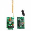
APC220 Wireless Transceiver Module Kit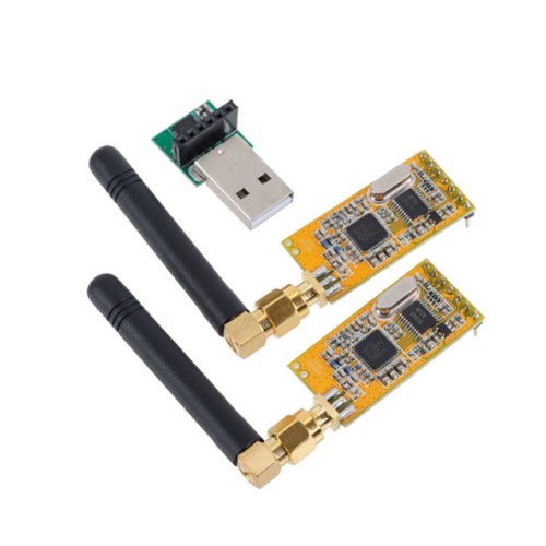
We can build electronics projects just as easy as piling bricks. Arduino and community have made the programming much easier than ever before. How about some elixir on hardware part? Maybe it is not yet convenient to make complex interfaces, but we can at least start from the most commonly used modules.
By using electronic bricks, you may connect Arduino compatible boards easily with various digital, analog and I2C/Uart interfaces. These the breadboard-less firm connection are prepared to extensive modules like poteniometers, sensors, relays, servos...even buttons, just plug and play.
Each terminal module has buckled port with VCC, GND and Output, which has corresponding port on the sensing board, with a plain 2.54mm dual-female cable you may start playing already. Buckled brick cables are like cement for bricks, make the connections easier, secure and more professional looking.
Parameter:
1、Power:20mW
2、Optional Interface:UART, RS485 / RS232
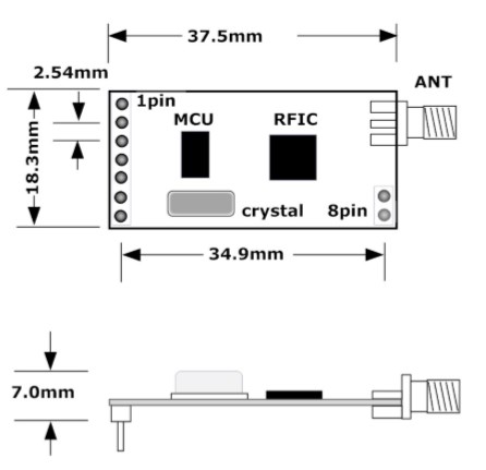
3、Size:37.5×18.3×7.0 mm
4、Transmission Distance:800m - 1200m (2400bps)
5、Working Frequency:470-510MHz (1KHz stepping)
6、More Than 100 Channels
7、GFSK Modulation System
8、Efficient circulatory interwoven error correction coding
9、Flexible software programming options setting
10、UART/TTL interface
11、256bytes data buffer
12、Suitable for large amount of data transmission
13、Built-in watchdog, ensure long-term and reliable operation
14、On-line modification Settings
Size:
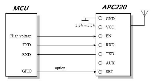
Connection:
In the previous article, we have discussed how to use the RF module to control Arduino wirelessly. Its principle is similar to a remote control, which has 4 buttons for RF wireless remote control. However, on occasions of data transmission, such a solution becomes less suitable, for example when you want to send PC the data that Arduino collected from light sensors. It is technically known as the wireless data transmission. At present, there are many solutions for wireless data transmission. A very simple way is connecting with the Arduino using APC220 to send data via serical port. Although the data transmission speed may slow (limited by the serial port baud rate) ,it is a simple and pratical way.No wonder that many netizens recommended the inclusion of such Arduino module support.
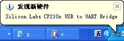
Manufacturers do not give any datasheet or material to us. Fortunately, some can be found on the network. Meanwhile learn by researching. First, USB adapter from manufacturer seems not to match APC220 because the number of pins is different. Maybe because it has to be compatible with other different products, or at least it is not specially designed for the APC220. USB adapter used CP2102 chip. Download the appropriate drivers in Silicon Laboratories.
After driver installation is complete, insert USB adapter into the PC's USB interface, Windows will be prompted to find new hardware, then finsh installation and configuration accordingly:
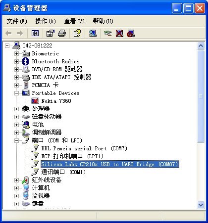
When Windows prompts that you can use the hardware. Below the Device Manager's "Ports (COM & LPT)" is CP2102 virtual serial port:
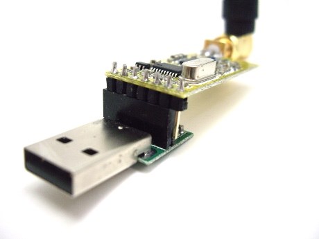
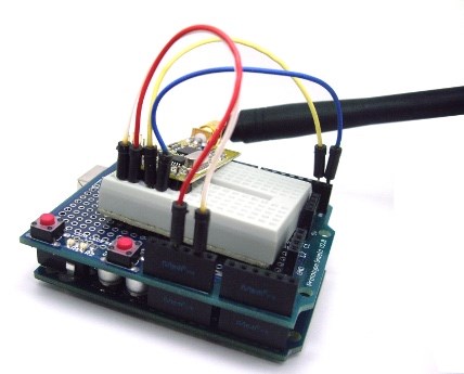
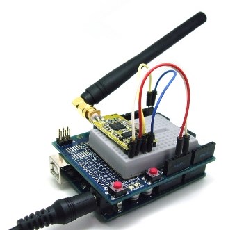
APC220 module can now be connected to a USB adapter. As pin number of USB adapter and APC220 is different, pay attention to the insert location:
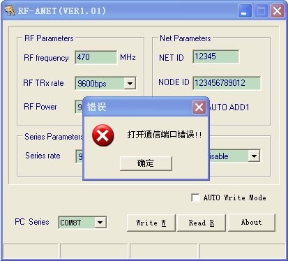
Open setup program "RF-ANET" gotten from APC220 manufacture. CP2102 has found the default serial port "COM87". However, RF-ANET can not open the port:
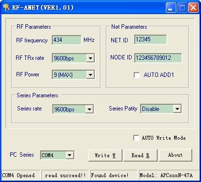
In the Device Manager, set serial port to COM4 , re-insert the USB adapter and open RF-ANET , click the "Read R" button. Everything is all right. The status bar displays "read succeed!", which means we are able to communicate with APC220.
Then we finished setup work on PC side. Now come to Arduino side. APC220 module has 4 connection wires to Arduino : 5V, GND, TX and RX. Note that APC220 and Arduino are a separate serial device, so connect TX on the Arduino to RX on APC220 and conncet RX on Arduino to TX on APC220:
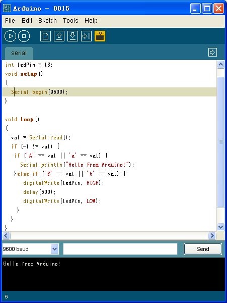
APC220 module's default baud rate is 9600. Let's test it with the following code.
Note that: when downloading process to Arduino, break the connection of TX and RX on APC220, otherwise downloading will be wrong.
int val = 0;
}
In summary, now that we have respectively connected Arduino and PC to APC220 module, and also has written test code to Arduino . While everything is ready, we can start the tests. First, we have to use an external power supply to powerArduino , because if the USB cable is connected, FT232 module will be activated, and then FT232 serial port and ACP220 serial port will conflict, leading to communication failure:
Put powed-on Arduino into a corner of the room. Then configure the PC. Through its USB adapter, APC220 module works like a serial port. So we can use Arduino 's development environment to test.In this case your PC is no longer connected to Arduino, but to APC220 USB adapter. After APC220 USB adapter's connection, open Arduino , in the "Tools" -> "Serial Ports" menu, select "COM4" (in line with the previous settings). Then open "Serial Monitor" in Arduino , send the A character. PC will receive "Hello from Arduino !" from Arduino . Send the B characters, then No. 13 LED on the Arduino is lighted(continuous 0.5 seconds):

Join our newsletter today, to get latest product information and promotion code.
 |
 |
|

|