


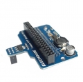
Arduino 4 Route MOSFET Button IRF540 V4.0
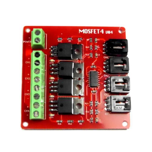
This item is the updated version of Arduino 4 Route MOSFET Button IRF540
MOSFET is an electronic devices with good switching characteristics. It is widely used in circuits, such as power supplies switching ,motor drives, lighting dimmer and so on. Relay is another kind of module with switching characteristics. Since relay works relying on mechanical contacts to open or shut. In this way it s will inevitably lead to relay's stopping working while switching time is too short. And papa sound made by relay in some situations is annoying.
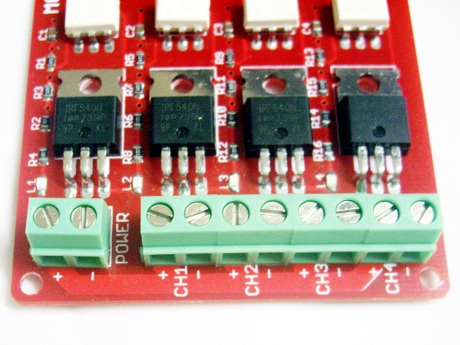
We designed a 4-channel MOSFET switch. It can supply up to four groups of electronic switches to control different circuit blocks respectively. Limited by the working priciples, MOSFET can only be used to control the DC circuit, such as DC-LED screen and so on, but not suitable for AC circuit control.
In some extreme cases,It can be used to control 100V/33A DC circuit. However, it is suggested that the controlled DC voltage is more than 9V.
.jpg)
This item have exact same function as the old version, so please refer to more information about useage on Arduino 4 Route MOSFET Button IRF540 as below :
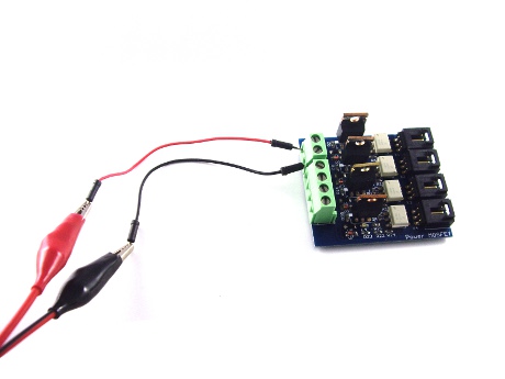
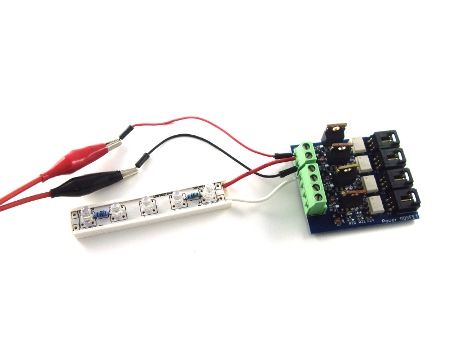
It takes some work to connected to the controlled part. Take controlling 12V LED lights as an example. First connect to the power through the positive (+) and negative (-).
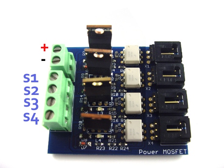
Then connect the LED's positive(+) with the module's positive (+), and LED 's negative terminal is connected to switch 1 (S1):
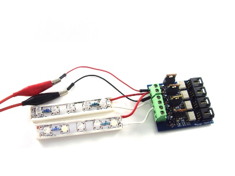
If controlling other LED lights at the same time, connect LED's positive to the module's positive (+), and their negative terminals are in turn connected to switch 2 (S2), Switch 3 (S3), Switch 4 (S4):
int s1Pin = 6;
int s2Pin = 7;
void setup() {
pinMode(s1Pin, OUTPUT);
pinMode(s2Pin, OUTPUT);
}
void loop() {
int i;
digitalWrite(s1Pin, HIGH);
digitalWrite(s2Pin, HIGH);
delay(500);
digitalWrite(s2Pin, LOW);
delay(500);
for (i = 0; i < 10; i ++) {
digitalWrite(s1Pin, HIGH);
delay(500);
digitalWrite(s1Pin, LOW);
delay(500);
}
for (i = 0; i < 100; i ++) {
digitalWrite(s2Pin, HIGH);
delay(50);
digitalWrite(s2Pin, LOW);
delay(50);
}
}
Join our newsletter today, to get latest product information and promotion code.
 |
 |
|

|